+86 15633683072
Choosing an automatic girth welding machine involves more than matching the equipment to a pipe's outside diameter. Wall thickness, joint preparation, welding position, workpiece accessibility, and production volume all influence the final choice.
For example, a pipe spool in a workshop may be welded using a rotating system, while a large pipeline or installed tank may require a carriage that travels around a stationary workpiece. Selecting the wrong configuration can increase setup time, restrict torch access, and make weld quality harder to maintain.
This guide explains how to select equipment for different pipe girth welding applications, compare track-guided and magnetic systems, and evaluate the factors that matter before purchasing.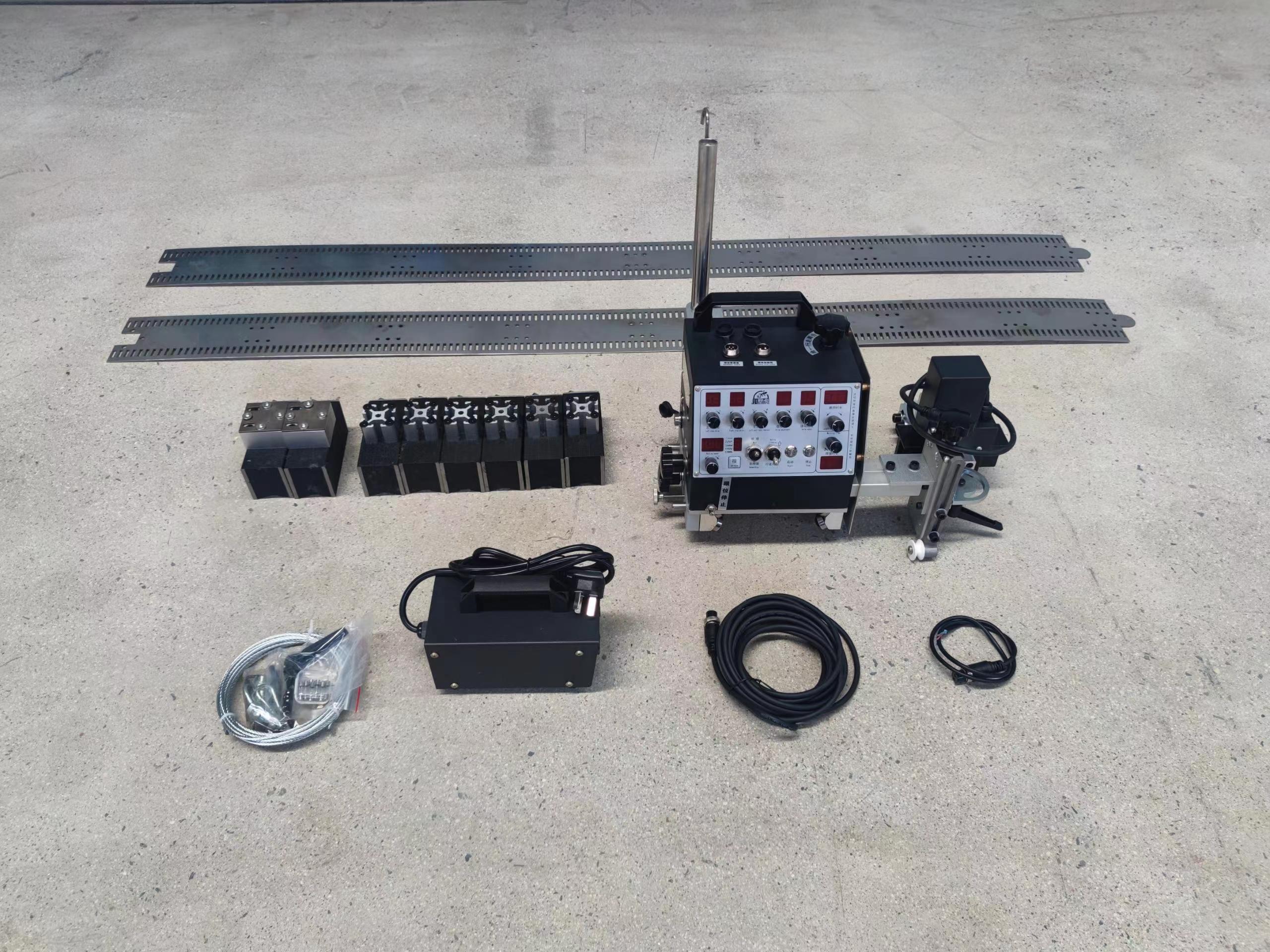
An automatic girth welding machine automates circumferential welding along the joint between cylindrical components, including pipes, tanks, and pressure vessels. Depending on its configuration, it may control torch travel, welding speed, oscillation, or other process parameters.
Pipe girth welding is common in pipeline fabrication, industrial piping, pressure vessel manufacturing, and tank construction.
The main equipment configurations are:
Track-guided welding carriage: Travels along a track installed around or alongside the workpiece.
Magnetic welding tractor: Uses magnetic attachment to travel on a suitable ferromagnetic surface.
Rotating-workpiece system: Rotates the workpiece while the welding torch remains in a controlled position.
These systems are not interchangeable. The right choice depends on whether the workpiece can rotate, how the welding path is accessed, and how frequently the same joint configuration is produced.
Start with the actual workpiece dimensions, not just the machine's advertised maximum diameter.
Pipe diameter affects carriage travel, track installation, and torch access. Wall thickness influences heat input, welding parameters, pass sequence, and total cycle time.
When evaluating a large diameter pipe girth welding machine, confirm:
Minimum and maximum workpiece diameters.
Wall thickness and joint geometry.
Whether single-pass or multi-pass welding is required.
Available clearance around the joint.
Required travel speed and torch adjustment range.
A machine's maximum diameter rating does not prove that it can handle every joint within that range. The supplier should confirm suitability for the actual workpiece and welding procedure.
If the workpiece can rotate safely, a welding rotator or positioner may keep the joint in a more favorable welding position. This can simplify torch control and improve consistency when the system is correctly configured.
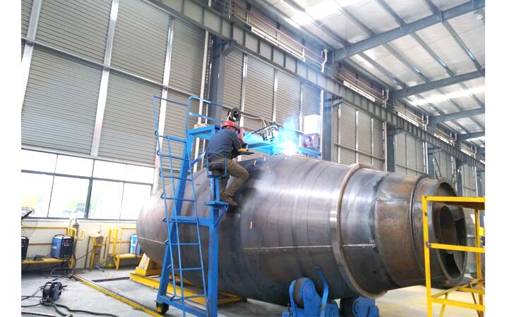
For large pipes, installed pipelines, or heavy tanks, rotation may be impractical because of weight, dimensions, supports, or site restrictions. In these cases, an automatic girth welding machine that travels around the stationary workpiece may be more practical.
Before choosing equipment, determine whether the job is best handled by rotating the workpiece or moving the welding head around it.
Track-guided and magnetic systems address different production needs.
A welding track carriage follows a dedicated track installed along the required welding path. A properly installed and aligned track provides a defined travel route and can support repeatable torch movement.
It is worth considering when:
Similar workpieces are welded repeatedly.
A defined travel path is important.
The production process can accommodate track installation.
The track can be securely mounted around the joint.
The main consideration is setup time. Track alignment, attachment, and repositioning can add work, particularly for one-off jobs. For repetitive production, however, the same setup may be reused.
For a detailed comparison, see track-guided and magnetic welding carriages, linked to the published article Welding Track Carriage vs. Magnetic Welding Carriage: Which One Fits Your Job?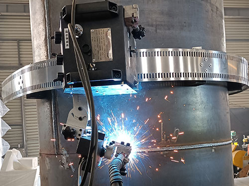
A magnetic welding tractor uses magnetic attachment to travel on a suitable ferromagnetic surface. It can reduce the need for a conventional fixed track when the workpiece geometry and surface conditions permit secure movement.
A magnetic welding tractor may be suitable for certain large steel pipes and tanks, but check:
Whether the material is ferromagnetic.
Whether the surface allows secure magnetic contact.
Whether curvature, coatings, or irregularities affect attachment.
Whether the carriage can complete the travel path safely.
Whether the torch can reach the joint without interference.
Conventional magnetic systems generally cannot rely on sufficient holding force on aluminum or austenitic stainless steel. Confirm material compatibility and attachment requirements with the manufacturer before selecting the equipment.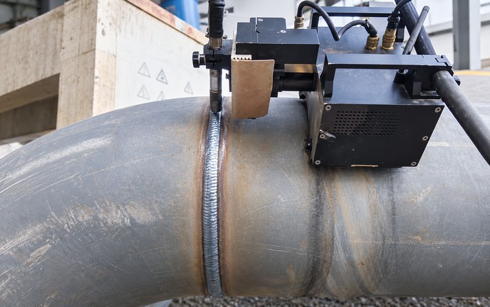
The machine must match the welding procedure as well as the workpiece dimensions. Depending on the material, thickness, joint design, and quality requirements, the process may involve TIG, MIG/MAG, or another suitable method.
When evaluating an automatic welding tractor for pipe, confirm which functions are included:
Travel speed control.
Torch angle and position adjustment.
Weaving or oscillation, where required.
Arc voltage control or AVC, where supported.
Multi-pass operation and repeatable parameter settings.
Compatibility with the selected welding power source.
Not every carriage includes all these functions. Some primarily automate travel, while more integrated systems offer additional motion and process control.
Joint preparation is equally important. Poor alignment, inconsistent root gaps, or unsuitable bevel geometry can cause defects that automation alone cannot correct. Evaluate the carriage alongside the welding power source, fixtures, fit-up procedure, and inspection requirements.
Travel speed alone is not a reliable measure of productivity. The complete cycle includes preparation, track or carriage setup, alignment, parameter adjustment, welding, repositioning, inspection, and possible repair.
For repetitive production, a track-guided system may justify its setup time through repeatability. For field work or large stationary structures, a magnetic welding tractor may reduce track-installation requirements when the surface is suitable.
Before purchasing, clarify the setup time, operating environment, operator adjustments, maintenance requirements, and training needs. Field applications also require attention to access, power supply, cable routing, environmental exposure, and safe attachment.
| Factor | Track-guided carriage | Magnetic welding tractor | Rotating-workpiece system |
|---|---|---|---|
| Travel method | Follows an installed track | Travels on a suitable magnetic surface | Workpiece rotates relative to the torch |
| Setup consideration | Track installation and alignment | Surface compatibility and attachment | Workpiece support and rotation |
| Potential advantage | Defined, repeatable travel path | May reduce track installation | Can simplify welding position |
| Main limitation | Setup and repositioning time | Not suitable for every material or surface | Large or installed workpieces may be difficult to rotate |
| Typical application | Repetitive circumferential welding | Suitable stationary steel pipes and tanks | Workshop pipe spools and rotatable components |
Use this comparison to shortlist the equipment type, then verify the actual machine specifications and welding requirements.
For large workpieces, evaluate the equipment under conditions representative of the intended production process.
Confirm that the carriage can complete the required circumference without collision, cable interference, loss of access, or an unsuitable torch angle. For track-guided systems, inspect track installation and alignment. For magnetic systems, verify secure attachment on the actual workpiece surface.
Use representative material, dimensions, and joint preparation whenever possible. Confirm that the machine's travel control and other functions are compatible with the intended welding procedure.
Assess the test weld against the project's applicable acceptance criteria. Depending on the application, inspection may include visual examination and specified nondestructive testing. A successful travel demonstration alone does not prove that the weld meets the required quality level.
Record setup time, arc-on time, pass changes, repositioning, inspection, and repair where applicable. This provides a more realistic productivity comparison than nominal travel speed alone.
For more information on automating large joints, see automating large-diameter pipe circumferential welds, linked to the published article How to Automate Circumferential Welds on Large-Diameter Pipes.
Choosing by maximum diameter alone: Wall thickness, joint geometry, torch access, and welding position also matter.
Assuming magnetic attachment works on every metal: Material and surface compatibility must be verified.
Ignoring setup and alignment: Poor track installation or joint fit-up can undermine automation.
Expecting automation to eliminate defects: Results still depend on the welding procedure, preparation, and operator setup.
Comparing travel speed alone: Setup, multi-pass welding, inspection, and repair affect overall output.
It automates circumferential welding on pipes, tanks, and pressure vessels. Depending on the configuration, it controls torch travel or coordinates welding with workpiece rotation.
Consider diameter, wall thickness, material, joint design, welding process, and production volume. Then determine whether the workpiece can rotate or must remain stationary before comparing track-guided, magnetic, and rotating-workpiece systems.
A track carriage follows an installed track, while a magnetic welding tractor uses magnetic attachment on a suitable ferromagnetic surface. The former requires track installation; the latter requires compatible material and secure contact.
Suitability depends on the stainless steel grade and attachment design. Conventional magnetic systems generally cannot rely on sufficient holding force on austenitic stainless steel. Verify compatibility with the manufacturer.
Some configurations are suitable for field applications, depending on access, surface conditions, power supply, safety requirements, and welding process. Confirm these factors before purchase.
No. Automation can improve travel consistency, but weld quality still depends on joint preparation, welding parameters, equipment setup, operator competence, and inspection.
Choosing an automatic girth welding machine means matching the equipment to the complete welding operation, not just the pipe diameter. Track-guided carriages can support repeatable travel, magnetic welding tractors can reduce track-installation requirements on compatible steel surfaces, and rotating-workpiece systems can simplify welding when safe rotation is possible.
For reliable pipe girth welding, evaluate the workpiece, joint preparation, access, welding procedure, setup time, and inspection requirements together. A representative production test and a full-cycle productivity assessment provide a more dependable basis for selection than a diameter rating or travel-speed claim alone.
Zhengzhou Kehui Technology Co., Ltd
Email: info@zzkehui.com





 Chinese
 English
 OA
OA Current location:
 Concrete Mixer Drum Robotic Welding Solutions
 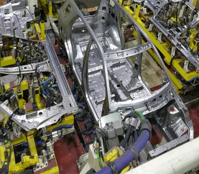 Automobile Body Production Line Welding Fixtures
 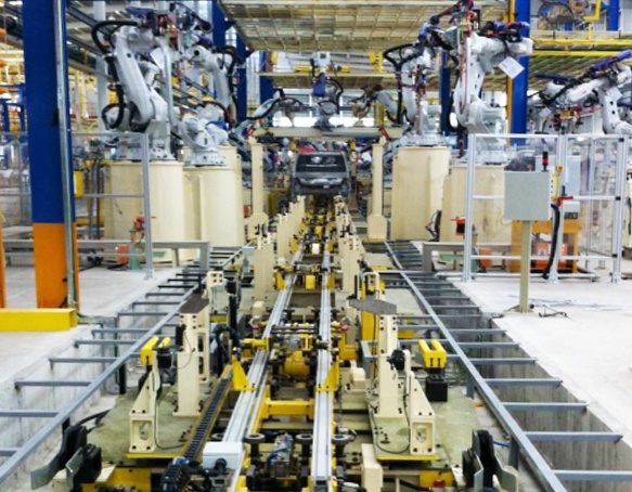 Automotive Body Welding Automated Manufacturing Solutions
 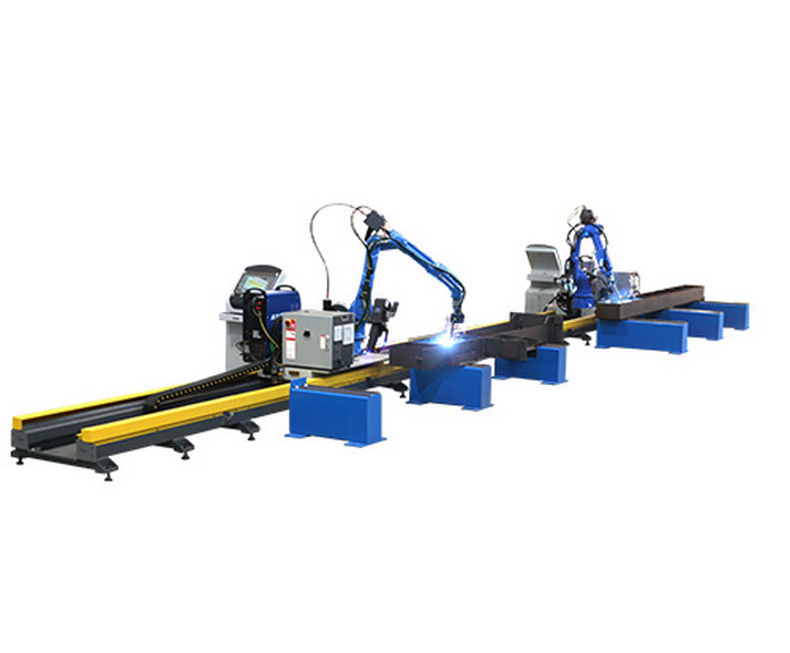 Free-Teaching Programming Welding Robot Cell For I Beam Welding
 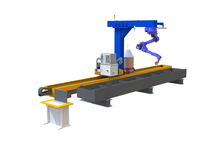 No Programming Required Robotic Welding Systems for H beam Welding Line